 |
 |
 |
 |
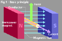

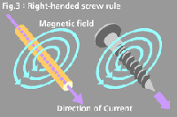
flow by the right-handed screw rule.
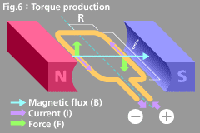
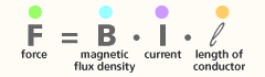
Electromagnetic force is obtained from the
equation;
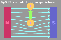
The torque produced by the single conductor is obtained from the equation;
�H �@�@�@�@�@�EF (force)
�@�@�@�@�@�H �ER (distance from the center conductor)
Here, there are 2 conductors present.
![]()
Term |
Symbol |
Unit |
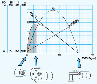
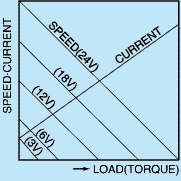
Various symbols and units
are used to indicate motor performance. The figure provided above
classifies them by input (electric energy) and output (mechanical
energy). See the list on the left for the details.
(*1) It indicates what percentage of the electric energy |
Input |
P |
W |
|
Output |
P |
W |
|
Maximum output |
Pmax. |
W |
|
Voltage |
V |
V |
|
Current |
I |
A |
|
No-load current |
I0 |
A |
|
Stall current |
Is |
A |
|
Efficiency (*1) |
�b |
% |
|
Maximum efficiency |
�bmax. |
% |
|
Speed |
N |
r/min (*2) |
|
No-load speed |
N0 |
r/min |
|
Torque |
T |
mN�Em, g�Ecm |
|
| Stall torque |
Ts |
mN�Em, g�Ecm |
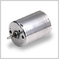
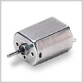
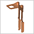
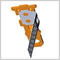
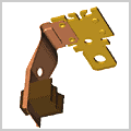
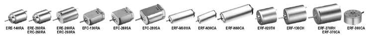
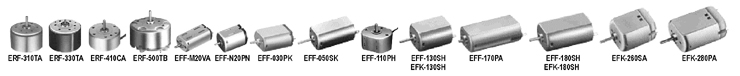
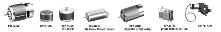
| This content shows the types of our motors. Our motor type code is based on the classification shown in this content. |
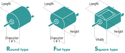
| Our motors are classified into three types by the motor-housing shapes of "Round type", "Flat type" and "Square type". |
 |
 |
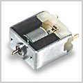 |
Round type |
Flat type |
Square type |
 |
Metal
Brush The brush that integrates with a terminal easily and used mostly for our economical models. Also named sheet brush. |
 |
Precious
Metal Brush The brush for which special precious metal is employed at the slide-contact portion with the commutator, and mainly used for our motors with low current and low output under low voltage. Also named a fork brush by its shape. |
 |
Carbon
Brush The brush for which a carbon is employed at the slide-contact portion with the commutator and fixed to a elastic brush-arm to have electrical conduction, and mainly used for our motors with high current and high output under high voltage. |
|
| ��For more information, please contact us directly by sales02@telstar-tech.com.tw or through our sales and representative offices overseas. |

| MODEL
|
SIZE
(mm) |
WEIGHT |
VOLTAGE |
NO
LOAD |
AT
MAXIMUM EFFICIENCY |
STALL |
|||||||||
| HOUSING
DIAMETER |
HOUSING LENGTH |
OPERATING RANGE |
NOMINAL |
SPEED |
CURRENT |
SPEED |
CURRENT |
TORQUE |
OUTPUT |
TORQUE |
CURRENT |
||||
| g |
rpm |
A |
rpm |
A |
g�Dcm |
g�Dcm |
W |
g�Dcm |
g�Dcm |
A |
|||||
| EFA-130RA-2270 |
15.1x�X20.1 |
25.0 |
17 |
1.5��3.0 |
1.5V |
9100 |
0.20 |
7000 |
0.66 |
6.0 |
0.59 |
0.43 |
26 |
2.55 |
2.20 |
| EFA-260RA-2670 |
18.3x�X24.2 |
26.9 |
28 |
1.5��3.0 |
3V |
12100 |
0.21 |
10000 |
1.00 |
15 |
1.47 |
1.54 |
92 |
9.02 |
4.80 |
| EFA-280RA-2865 |
18.3x�X24.2 |
30.5 |
35 |
1.5��3.0
|
3V |
10500 |
0.17 |
8800 |
0.89 |
18 |
1.76 |
1.62 |
114 |
11.2 |
4.68 |
| EFF-M20VA-8Z130 |
8.0x�X10.0
|
15.0 |
4 |
2��3 |
3V |
15200 |
0.045 |
11800 |
0.16 |
1.6 |
0.16 |
0.19 |
8 |
0.78 |
0.55 |
| EFF-N20PN-13115 |
10.0x�X12.0 |
15.0 |
5 |
1.5��3.0 |
2.4V |
15800 |
0.096 |
12200 |
0.33 |
2.8 |
0.27 |
0.35 |
13 |
1.27 |
1.15 |
| EFF-N30VA-09210 |
10.0x�X12.0 |
20.0 |
7.5 |
2��5 |
2.5V |
5200 |
0.019 |
4000 |
0.066 |
1.8 |
0.18 |
0.074 |
8 |
0.78 |
0.23 |
| EFF-030PK-08250 |
12.0x�X15.5 |
18.6 |
11 |
1��6 |
2.5V |
4100 |
0.028 |
2900 |
0.071 |
2.1 |
0.21 |
0.062 |
8 |
0.78 |
0.18 |
| EFF-050SK-11170 |
12.0x�X15.5 |
26.9 |
18 |
1.5��9.0 |
7V |
10300 |
0.046 |
8500 |
0.17 |
7.0 |
0.69 |
0.31 |
46 |
4.51 |
0.82 |
| EFF-110PH-08280 |
13.0x�X16.0 |
11.4 |
7.5 |
1��3 |
3V |
8000 |
0.031 |
5800 |
0.085 |
1.6 |
0.16 |
0.095 |
6 |
0.59 |
0.23 |
| EFF-130SH-11340 |
15.4x�X20.4 |
25.1 |
24 |
3��12 |
9V |
7300 |
0.035 |
5900 |
0.15 |
12 |
1.18 |
0.73 |
67 |
6.57 |
0.68 |
| EFF-170PA-3724 |
14.5x�X18.7 |
32.1 |
33 |
1.0��1.5 |
1.2V |
7800 |
0.33 |
6500 |
1.62 |
18 |
1.76 |
1.20 |
110 |
10.8 |
8.00 |
| EFF-180SH-2657 |
15.4x�X20.4 |
32.1 |
32 |
1��3 |
2.4V |
7700 |
0.13 |
6400 |
0.70 |
15 |
1.47 |
1.19 |
107 |
10.5 |
3.80 |
| EFF-270PA-4031 |
17.9x�X21.2 |
30.0 |
34 |
1.2��2.0 |
1.2V |
7000 |
0.70 |
5800 |
1.60 |
20 |
1.96 |
1.19 |
115 |
11.3 |
8.00 |
| EFC-130RA-14150 |
15.1x�X20.1 |
25.0 |
17 |
4.5��6.0 |
4.5V |
13200 |
0.14 |
9900 |
0.42 |
7.5 |
0.74 |
0.76 |
30 |
2.94 |
1.25 |
| EFC-260SA-2670 |
18.3x�X24.2 |
26.9 |
28 |
3��6 |
4.5V |
14000 |
0.27 |
11600 |
1.33 |
29 |
284 |
3.45 |
180 |
17.6 |
6.70 |
| EFC-280PT-20150 |
18.3x�X24.2 |
30.5 |
35 |
9��15 |
12V |
12500 |
0.12 |
10500 |
0.67 |
40 |
3.92 |
4.31 |
270 |
26.5 |
3.70 |
| EFC-280SA-18165 |
18.3x�X24.2 |
30.5 |
35 |
10��15 |
12V |
12400 |
0.10 |
10700 |
0.51 |
35 |
3.43 |
3.84 |
260 |
25.5 |
3.40 |
| EFK-130RD-09490 |
15.4x�X20.4 |
25.0 |
24 |
9��15 |
12V |
8800 |
0.030 |
6800 |
0.11 |
8.0 |
0.78 |
0.56 |
38 |
3.72 |
0.38 |
| EFK-130RH-09490 |
15.4x�X20.4 |
25.1 |
24 |
6��18 |
12V |
9000 |
0.034 |
6900 |
0.12 |
8.5 |
0.83 |
0.60 |
40 |
3.92 |
0.41 |
| EFK-180SH-09450 |
15.4x�X20.4 |
32.1 |
32 |
12��24 |
24V |
9200 |
0.025 |
7700 |
0.11 |
20 |
1.96 |
1.58 |
130 |
12.7 |
0.63 |
| EFK-260SA-09450 |
18.3x�X24.2 |
26.9 |
29 |
12��24 |
12V |
5700 |
0.030 |
4400 |
0.11 |
15 |
1.47 |
0.68 |
74 |
7.25 |
0.42 |
| EFK-280PA-20150 |
18.3x�X24.2 |
30.5 |
36 |
10��15 |
12V |
12000 |
0.10 |
10300 |
0.70 |
45 |
4.41 |
4.75 |
325 |
31.9 |
3.80 |
| ERE-140RA-2270 |
�X21.0 |
25.0 |
19 |
1.5��3.0 |
1.5V |
8100 |
0.21 |
6100 |
0.66 |
6.5 |
0.64 |
0.41 |
28 |
2.74 |
2.10 |
| ERE-260RA-2670 |
�X23.8 |
26.9 |
28 |
1.5��3.0 |
3V |
12300 |
0.20 |
10100 |
0.97 |
15 |
1.47 |
1.55 |
90 |
8.82 |
4.73 |
| ERD-280RA-2865 |
�X23.8 |
30.5 |
42 |
1.5��3.0 |
3V |
9200 |
0.16 |
7800 |
0.85 |
20 |
1.93 |
1.60 |
130 |
12.7 |
4.70 |
| ERF-M50WA-1645 |
�X10.1 |
25.0 |
7.9 |
1.2��2.4 |
2.4V |
16700 |
0.075 |
13600 |
0.35 |
3.0 |
0.29 |
0.42 |
19 |
1.86 |
1.93 |
| ERF-N30CA-11150 |
�X12.1 |
19.5 |
8 |
2��5 |
5V+1�[ |
19900 |
0.075 |
14900 |
0.25 |
3.7 |
0.36 |
0.57 |
15 |
1.47 |
0.79 |
| ERF-N60CA-1955 |
�X12.1 |
30.0 |
13 |
1��3 |
2.4V |
12700 |
0.13 |
10100 |
0.51 |
6.0 |
0.59 |
0.62 |
32 |
3.14 |
2.04 |
| ERF-020TH-10210 |
�X17.1 |
18.0 |
16 |
2��5 |
4.5V |
12600 |
0.058 |
9500 |
0.18 |
3.9 |
0.38 |
0.38 |
16 |
1.57 |
0.59 |
| ERF-130CH-12250 |
�X17.1 |
22.8 |
18 |
2.0��7.5 |
3.5V |
4700 |
0.028 |
3700 |
0.11 |
4.9 |
0.48 |
0.19 |
24 |
2.35 |
0.41 |
| ERF-3LOPA-12330 |
�X24.4 |
10.3 |
18 |
1��2 |
2V |
3700 |
0.038 |
2700 |
0.11 |
3.1 |
0.30 |
0.086 |
12 |
1.18 |
0.31 |
| ERF-300CA-14270 |
�X24.4 |
12.3 |
22 |
0.5��0.4 |
1.9V |
3500 |
0.032 |
2700 |
0.12 |
3.8 |
0.37 |
0.11 |
18 |
1.76 |
0.42 |
| ERF-300PA-11400 |
�X24.4 |
12.3 |
22 |
1��3 |
3V |
3000 |
0.015 |
2400 |
0.065 |
4.3 |
0.42 |
0.11 |
23 |
2.25 |
0.28 |
| ERF-310TA-11400 |
�X24.4 |
18.4 |
29 |
1��6 |
2.5V |
2800 |
0.017 |
2200 |
0.060 |
3.2 |
0.31 |
0.072 |
15 |
1.47 |
0.22 |
| ERF-320CH-12400 |
�X24.4 |
18.4 |
28 |
1��5 |
3V |
2700 |
0.019 |
2300 |
0.060 |
4.0 |
0.39 |
0.094 |
26 |
2.55 |
0.30 |
| ERF-330TA-11360 |
�X25.0 |
18.4 |
32 |
2��6 |
3.4V |
3400 |
0.015 |
2700 |
0.066 |
4.3 |
0.42 |
0.12 |
23 |
2.25 |
0.29 |
| ERF-270RH-12370 |
�X24.4 |
30.8 |
51 |
6��15 |
12V |
6200 |
0.028 |
5100 |
0.14 |
19 |
1.86 |
0.99 |
115 |
11.3 |
0.70 |
| ERF-370CA-15370 |
�X24.4 |
30.8 |
51 |
3��12 |
12V |
5600 |
0.025 |
4800 |
0.16 |
24 |
2.35 |
1.18 |
186 |
18.2 |
1.06 |
| ERF-370CN-11670 |
�X24.4 |
30.8 |
51 |
6��14 |
12V |
3200 |
0.013 |
2600 |
0.067 |
17 |
1.67 |
0.45 |
106 |
10.4 |
0.35 |
| ERF-410CA-12250 |
�X26.4 |
10.0 |
20 |
1��2 |
1.9V |
3700 |
0.029 |
2800 |
0.098 |
2.8 |
0.27 |
0.080 |
12 |
1.18 |
0.33 |
| ERF-500TB-14415 |
�X32.0 |
19.5 |
45 |
1.5��9.0 |
6V |
3700 |
0.028 |
3000 |
0.13 |
14 |
1.37 |
0.43 |
84 |
8.23 |
0.65 |
| ERD-180SA-2085 |
�X21.3 |
29.0 |
31 |
1.2��4.5 |
2.4V |
5300 |
0.052 |
4500 |
0.30 |
10 |
0.98 |
0.46 |
70 |
6.86 |
1.70 |
| ERC-260RA-18130 |
�X23.8 |
26.9 |
28 |
4.5��6.0 |
4.5V |
9800 |
0.14 |
7700 |
0.53 |
15 |
1.47 |
1.18 |
72 |
7.06 |
2.00 |
| ERC-280RA-2865 |
�X23.8 |
30.5 |
42 |
4.5��6.0 |
4.5V |
13600 |
0.27 |
11500 |
1.15 |
25 |
2.45 |
2.95 |
180 |
17.6 |
6.90 |
| ERK-270RH-2680 |
�X24.4 |
30.8 |
51 |
3��6 |
4.5V |
10200 |
0.12 |
8700 |
0.90 |
30 |
2.94 |
2.68 |
185 |
18.1 |
5.30 |
| ERK-370CA-18220 |
�X24.4 |
30.8 |
51 |
6��15 |
9V |
7000 |
0.060 |
6000 |
0.32 |
28 |
2.74 |
1.72 |
195 |
19.1 |
1.94 |
| ERK-384CA-16170 |
�X24.4 |
36.0 |
56 |
24��30 |
30V |
21000 |
0.15 |
16700 |
0.58 |
58 |
5.68 |
9.93 |
290 |
28.4 |
2.28 |
| ERK-P36CB-22210 |
�X60.7 |
25.4 |
260 |
9��14 |
14V |
2600 |
0.16 |
2100 |
0.58 |
200 |
19.6 |
4.31 |
1200 |
118 |
2.70 |
| ERS-360SH-2885 |
�X27.7 |
32.6 |
55 |
3��9 |
7.2V |
12500 |
0.36 |
11000 |
1.30 |
50 |
4.90 |
5.64 |
420 |
41.2 |
8.60 |
| ERS-365SA-1885 |
�X27.7 |
32.6 |
49 |
6��20 |
20V |
23200 |
0.24 |
18900 |
1.05 |
65 |
6.37 |
12.6 |
380 |
37.2 |
4.80 |
| ERS-365SH-2080 |
�X27.7 |
32.6 |
54 |
6��20 |
12V |
12800 |
0.19 |
1400 |
0.83 |
55 |
5.93 |
5.87 |
305 |
29.9 |
3.60 |

| MODEL
|
SIZE
(mm) |
WEIGHT |
VOLTAGE |
NO
LOAD |
AT
MAXIMUM EFFICIENCY |
STALL |
|||||||||
| HOUSING
DIAMETER |
HOUSING LENGTH |
OPERATING RANGE |
NOMINAL |
SPEED |
CURRENT |
SPEED |
CURRENT |
TORQUE |
OUTPUT |
TORQUE |
CURRENT |
||||
| g |
rpm |
A |
rpm |
A |
g�Dcm |
g�Dcm |
W |
g�Dcm |
g�Dcm |
A |
|||||
ERS-380SH-4045 |
�X27.2 |
37.8 |
71 |
3��9 |
7.2V |
16200 |
0.50 |
14000 |
3.29 |
110 |
10.8 |
15.8 |
840 |
82.3 |
21.6 |
ERS-385SA-2073 |
�X27.2 |
37.8 |
62 |
9��24 |
20V |
18300 |
0.21 |
15800 |
0.90 |
75 |
7.35 |
12.2 |
550 |
53.9 |
5.40 |
ERS-285SH-2270 |
�X27.2 |
37.8 |
70 |
6��24 |
20V |
16400 |
0.18 |
1400 |
1.04 |
95 |
9.31 |
13.6 |
670 |
65.7 |
6.20 |
ERS-540SH-5045 |
�X35.8 |
50.0 |
160 |
4.5��12 |
6V |
8400 |
0.26 |
7200 |
3.91 |
220 |
21.6 |
16.2 |
1600 |
157 |
24.6 |
ERS-545SH-5018 |
�X35.8 |
50.0 |
156 |
4.5��12 |
12V |
24000 |
1.30 |
20600 |
7.50 |
300 |
29.4 |
63.4 |
2180 |
214 |
45.0 |
ERS-550SH-7522 |
�X35.8 |
57.0 |
215 |
3.6��9.6 |
7.2V |
15800 |
1.80 |
13500 |
10.9 |
410 |
40.0 |
66.4 |
2900 |
284 |
66.5 |
ERS-555SH-2670 |
�X35.8 |
57.0 |
209 |
9.6��30 |
24V |
9100 |
0.21 |
7800 |
1.27 |
280 |
27.4 |
22.4 |
2000 |
196 |
7.70 |
ERS-750SF-8027 |
�X42.2 |
60.0 |
270 |
6��12 |
9.6V |
18600 |
1.95 |
15900 |
11.8 |
520 |
51.0 |
84.8 |
3650 |
358 |
71.0 |
ERS-775SF-7513 |
�X42.2 |
67.0 |
320 |
6��15 |
12V |
18700 |
2.20 |
16000 |
13.6 |
710 |
69.6 |
117 |
5100 |
500 |
84.0 |
ERS-775VF-909 |
�X42.2 |
67.0 |
350 |
6��12 |
12V |
22600 |
4.50 |
18900 |
23.0 |
1000 |
98.0 |
194 |
6750 |
662 |
112 |
ERS-865WE-A012 |
�X42.1 |
67.0 |
370 |
6.0��13.5 |
12V |
17000 |
3.50 |
15000 |
18.0 |
1000 |
98.0 |
154 |
9300 |
911 |
135 |
ESU-020SA-1665 |
9.5x�X18.0 |
18.9 |
9.5 |
1.2��1.5 |
1.5V |
11700 |
1.71 |
8800 |
0.50 |
3.0 |
0.29 |
0.27 |
13 |
1.27 |
1.55 |
ESH-030SA-08240 |
9.5x�X18.0 |
18.9 |
11 |
6��12 |
12V |
22300 |
0.080 |
16700 |
0.24 |
7.0 |
0.69 |
1.20 |
29 |
2.84 |
0.72 |
EFK-290PY-051000 |
17.9x�X21.2 |
42.5 |
50 |
100��120 |
100V |
6700 |
0.005 |
5600 |
0.018 |
28 |
2.74 |
27.7 |
105 |
10.3 |
0.09 |
ERT-553PF-11100 |
�X35.7 |
57.0 |
190 |
100��120 |
120V |
13000 |
0.080 |
10800 |
0.36 |
250 |
24.5 |
840 |
1750 |
172 |
2.00 |
MODEL |
SIZE
(m/m) |
WEIGHT |
RATED VOLTAGE |
WORKING VOLTAGE |
RATED
LOAD |
RATED SPEED |
RATED
LOAD CURRENT |
LOAD FLUCUATION (TYPE) |
STARTING TORQUE (MIN) |
|||
| HOUSING DIAMETER |
HOUSING LENGTH |
|||||||||||
| g |
g�Dcm |
mN�Dm |
rpm |
mA
(TYPE) |
rpm/g�Dcm |
g�Dcm |
mN�Dm |
|||||
EEG-520ED(3B) |
�X30.0 |
24.0 |
50 |
13.2 |
8.4��16 |
10 |
0.98 |
2400��2% |
74 |
2.5 |
60at8.4V |
5.88at8.4V |
EEG-530AD-6F(6B) |
�X35.0
|
25.0 |
70 |
6 |
4.2��7.5 |
8.0 |
0.78 |
2400��2% |
132 |
9.0 |
38at4.2V |
3.72at4.2V |
EEG-530AD-9F(9B) |
70 |
9 |
6��11 |
8.0 |
0.78 |
2400��2% |
92 |
9.0 |
50at 6.0V |
4.90at6.0V |
||
EEG-530AD-2F(2B) |
70 |
12 |
8.4��15 |
8.0 |
0.78 |
2400��2% |
73 |
9.0 |
60at8.4V |
5.88at8.4V |
||
EEG-530KD-9F(9B)
|
�X35.0 |
25.0 |
70 |
9 |
6.3��11.7
|
10 |
0.98 |
1600 |
109 |
5.0 |
40 |
3.92 |
3200 |
116 |
7.0 |
||||||||||
| EEG-530KD-2F(2B) |
70 |
12 |
8.4��15.6 |
10 |
0.98 |
1600 |
83 |
5.0 |
50 |
4.90 |
||
3200 |
89 |
7.0 |
||||||||||
EEG-530YD-9BH |
�X35.0 |
25.0 |
70 |
9 |
6.3��11.7 |
10 |
0.98 |
2000 |
128 |
1.5 |
50 |
4.90 |
4000 |
140 |
4.0 |
||||||||||
EEG-530YD-2BH |
70 |
12 |
8.4��15.6 |
10 |
0.98 |
2000 |
99 |
1.5 |
55 |
5.39 |
||
| 4000 |
108 |
4.0 |
||||||||||
MODEL |
SIZE |
VOLTAGE |
FREQUENCY |
SPEED |
CURRENT |
INPUT |
PULL
OUT TORQUE |
||
OPERATING
RANGE |
NOMINAL |
||||||||
(m/m) |
AC�DV |
AC�DV |
Hz |
rpm |
A |
W |
g�Dcm |
mN�Dm |
|
| ECO-241PA-112700 | 27.2��44.5��32.8 |
220��240 |
230 |
50 |
3000 |
0.10 |
10.0 |
330 |
32.3 |
| ECO-261PA-122100 | 27.2��44.5��39.2 |
220��240 |
230 |
50 |
3000 |
0.14 |
11.5 |
380 |
37.2 |
MODEL |
SIZE
(m/m) |
WEIGHT |
VOLTAGE |
NO
LOAD |
RATED
LOAD (*) |
STALL |
|||||
HOUSING
DIAMETER |
HOUSING
LENGTH |
NOMINAL |
SPEED |
CURRENT |
SPEED |
CURRENT |
CURRENT |
TORQUE |
|||
rpm |
A |
rpm |
A |
A |
Kg�Dcm |
mN�Dm |
|||||
EJC/LC-578VA-4720 |
30.3��39.0 |
72.0 |
520 |
12V |
92 |
1.30 |
58 |
6.40 |
24.0 |
93 |
9.12 |
EJD/LD-578VA-4720 |
515 |
||||||||||
 |
|
| |
If voltage in continuous applied to a motor in a locked rotor condition, the motor will heat up and fail in a relatively short time. Therefore it is important that there is some form of protection against high temperature rises. |
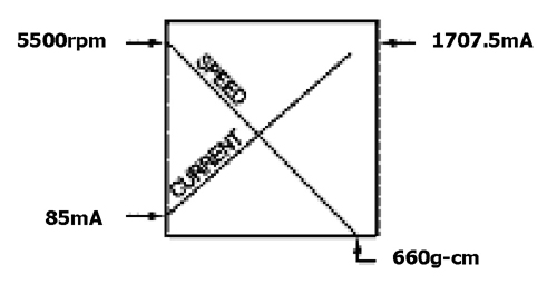
| A motor's basic rating point is slightly lower than its maximum efficiency point. | |
| Load torque can be determined by measuring the current drawn when the motor is attached to a machine whose actual load value is known. | |
| We will select the most suitable motor for your application after receiving your information. |
 |
|
 |
|
 |
|
 |
|
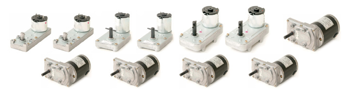
(Suitable for less than 2sec.on & long enough off time)
STANDARD TYPE:GM30,GT30,GM33GM35,GM35,GM35B,GM37,GT38,GM56,GM90
 |
|
 |
|
 |
|
| Protection against overload and locked rotor | |
|
|
| Protection against RFI/EMI caused by PWM control | |
|
|
| Precautions for instantaneous reversing and dynamic braking | |
|
|
| Vertical mounting with shaft up | |
|
|
| Speed detection and control | |
|
MODEL |
SIZE |
VOLTAGE |
RATIO |
SPEED (rpm) |
Rated Torque (Kg-cm) |
||||
| TYPE |
GEARHEAD |
SHAFT |
GEARMOTOR |
RANGE |
Rated |
||||
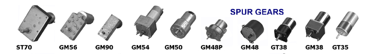
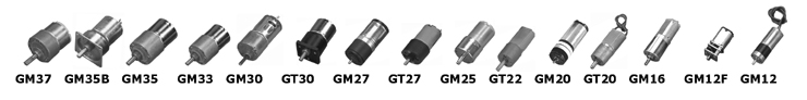
| GM12 | Spur Gear |
�X12��L13.9 |
�X2.0 |
�X12��L33.9 |
1.2-6V |
3V |
1/15�V1/280 |
45�V627 |
0.05-0.25 |
| GM12F | Spur Gear |
�X12��L9 |
�X3.0 |
�X12��L24.0 |
1.2-6V |
4.5V |
1/50�V1/298 |
40�V238 |
0.15-0.5 |
| GM16 | Spur Gear |
�X16��L20.6 |
�X3.0 |
�X16��L47.5 |
3-12V |
6V |
1/10.24�V1/540 |
20�V1074 |
0.04-0.8 |
| GM20 | Spur Gear |
�X20��L24.1 |
�X3.0 |
�X20��L56.2 |
3-24V |
12V |
1/10�V1/6000 |
0.8�V470 |
0.2-1.0 |
| GT20 | Spur Gear |
�X20��L20 |
�X5.0 |
�X20��L49 |
3-24V |
24V |
1/20�V1/500 |
26- 637 |
0.2-1.0 |
| GT22 | Spur Gear |
�X22��L21 |
�X6.0 |
�X22��L40 |
3-24V |
12V |
1/10�V1/200 |
38�V754 |
0.1-1.5 |
| GM25 | Spur Gear |
�X26.7��L18.2 |
�X4.0 |
�X26.7��L41.7 |
3-24V |
6V |
1/10�V1/1000 |
5.6�V560 |
0.1-2.0 |
| GM27 | Spur Gear |
�X26.7��L19.4 |
�X4.0 |
�X26.7��L48.9 |
3-24V |
12V |
1/10�V1/1000 |
7.4�V740 |
0.1-2.0 |
| GT27 | Spur Gear |
�X27��L20.3 |
�X3.0 |
�X27��L51.1 |
3-24V |
24V |
1/10�V1/300 |
14�V426 |
0.1-2.0 |
| GM30 | Spur Gear |
�X30��L23 |
�X4.0 |
�X30��L55.6 |
3-24V |
24V |
1/10�V1/300 |
17�V500 |
0.15-3.5 |
| GT30 | Spur Gear |
�� 30��L25.6 |
�X5.0 |
�� 30��L49.6 |
6-24V |
24V |
1/15�V1/500 |
8.5�V283 |
0.15-3.5 |
| GM33 | Spur Gear |
�X34.9��L24.5 |
�X5.0 |
�X34.9��L53.5 |
6-24V |
12V |
1/10�V1/3000 |
2�V600 |
0.4-6.0 |
| GM35 | Spur Gear |
�X37��L24.5 |
�X6.0 |
�X37��L54 |
6-24V |
12V |
1/10�V1/3000 |
2�V600 |
0.5-6.0 |
| GM35B | Spur Gear |
�� 43��L25.8 |
�X6.0 |
�� 43��L55.3 |
6-24V |
12V |
1/15�V1/494.55 |
12�V400 |
0.5-6.0 |
| GM37 | Spur Gear |
�X37��L19.3 |
�X6.0 |
�X37��L48.8 |
6-24V |
12V |
1/10�V1/3000 |
2�V600 |
0.5-6.0 |
| GT35 | Spur Gear |
�X37��L22.7 |
�X5.0 |
�X37��L51.7 |
6-24V |
12V |
1/9.9�V1/2900 |
2.06�V606 |
0.5-6.0 |
| GM38 | Spur Gear |
�� 42��L26 |
�X5.0 |
�� 42��L86 |
110/220VAC |
100V |
1/3�V1/150 |
10�V500 |
2.0-10 |
| GM38 | Spur Gear |
�� 42��L28.7 |
�X5.0 |
�� 42��L68.7 |
6-24V |
24V |
1/10�V1/3000 |
2�V600 |
2.0-10 |
| GT38 | Spur Gear |
�� 38��L25.7 |
�X6.0 |
�� 38��L55.2 |
6-24V |
12V |
1/10�V1/900 |
6.7�V600 |
0.5-7.0 |
| GM48 | Spur Gear |
�X48��L16 |
�X7.0 |
�X48��L44 |
110/220VAC |
220V |
1/10�V1/100 |
1�V60 |
7.0-10.0 |
| GM48P | Spur Gear |
�X62��65��L16 |
�X6.0 |
�X62.31��L39.7 |
6-24V |
24V |
1/10�V1/3000 |
1.0�V300 |
0.1-1.5 |
| GM50 | Spur Gear |
�X50��L34.5 |
�X6.35 |
�X50��L92.5 |
12-24V |
24V |
1/12.67�V1/152 |
28�V332 |
1.5-10.0 |
| GM54 | Spur Gear |
�� 60��L38.9 |
�X8.0 |
�� 60��L98.9 |
12-100V DC |
12V |
1/20�V1/160 |
33�V265 |
4.5-20.0 |
| GM56 | Spur Gear |
�� 56��L100 |
�X8.0 |
�� 56��L60.5 |
12-24V |
12/24V |
1/20�V1/300 |
2�V300 |
5.0-20.0 |
| ST70 | Spur Gear |
�� 70��L100 |
�X12 |
�� 70��L93 |
12-100V DC |
24V |
1/60�V1/800 |
3.4�V92.3 |
2.5-10.0 |
| GM90 | Spur Gear |
�� 40��L90 |
�X8.0 |
�� 40��L49.5 |
12-24V |
24V |
1/36�V1/500 |
10�V138 |
5.0-20.0 |
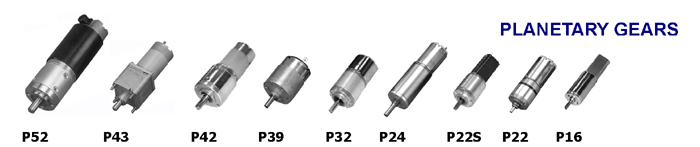
| P16 | Spur Gear |
�X16��L26 |
�X3.0 |
�X16��L46 |
3-24V |
12V |
1/4�V1/2000 |
3�V1500 |
1.0-3.0 |
| P22 | Planetary |
�X22��L25.5 |
�X3.0 |
�X22��L54.5 |
3-24V |
12V |
1/4.5�V1/483.66
|
11�V1133 |
0.1-1.5 |
| P22S | Planetary |
�X22��L26 |
�X4.0 |
�X22��L60 |
3-24V |
12V |
1/4�V1/2000 |
3�V1500 |
3.0-9.0 |
| P24 | Planetary |
�X23.7��L43.6 |
�X5.0 |
�X23.7��L72.6 |
3-24V |
12V |
1/4.5�V1/242.79 |
24.0�V1287 |
0.1-2.0 |
| P32 | Planetary |
�X32��L36 |
�X6.0 |
�X32��L62 |
3-24V |
12V |
1/5�V1/720 |
7�V1000 |
6.0-36.0 |
| P39 | Planetary |
�X39��L29 |
�X6.0 |
�X39��L46.5 |
12-24V |
12/24V |
1/10�V1/300 |
163�V570 |
0.5-6.0 |
| P42 | Planetary |
�X42��L60 |
�X8.0 |
�X42��L128 |
6-24V |
12V |
1/4�V1/3600 |
1.0�V1250 |
15.0-90.0 |
| P43 | Planetary |
��43��L32.7 |
�X8.0 |
��43��L82.7 |
6-24V |
12V |
1/14�V1/864 |
5.6�V346 |
1.0-20.0 |
| P52 | Planetary |
�X52��L58.45 |
�X12 |
�X52��L120.95 |
12-100V DC |
24V |
1/10�V1/180 |
16�V250 |
5.0-30.0 |
MODEL |
SIZE |
VOLTAGE |
RATIO |
SPEED (rpm) |
Rated Torque (Kg-cm) |
|||
| TYPE |
GEARHEAD |
SHAFT |
GEARMOTOR |
RANGE |
||||
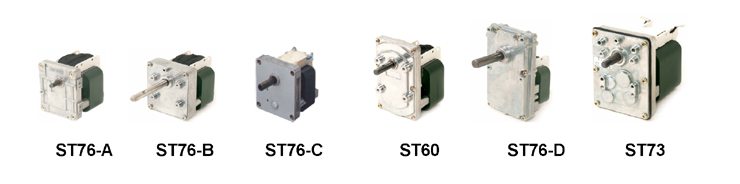
| ST60 |
Spur Gear |
��60��97 X L
20 |
�X8.0 |
��60��69��L 83 |
AC110/220V,60Hz |
1/10�V1/ 850 |
4- 342 |
5.0�V30.0 |
| ST73 | Spur Gear |
��73��95 X L
20 |
�X10.0 |
��73��95��L 105 |
AC110/220V,60Hz |
1/30-1/ 300 |
12-123 |
10.0�V90.0 |
| ST76-A | Spur Gear |
��76��60 X L
15 |
�X8.0 |
��76��60��L 60 |
AC110/220V,60Hz |
1/50-1/ 560 |
6-68 |
1.0�V6.0 |
| ST76-B | Spur Gear |
��76��64 X L
20 |
�X8.0 |
��76��64��L 80 |
AC110/220V,60Hz |
1/14�V1/ 580 |
6-248 |
2.0�V20.0 |
| ST76-C | Spur Gear |
��76��69 X L
20 |
�X8.0 |
��76��69��L 80 |
AC110/220V,60Hz |
1/10-1/ 500 |
6-342 |
5.0�V30.0 |
| ST76-D | Spur Gear |
��76��136 X
L 26 |
�X10.0 |
��76��136 X
L 26 |
AC110/220V,60Hz |
1/165-1/ 1100 |
3-20 |
20.0�V50.0 |
MODEL |
SIZE |
VOLTAGE |
RATIO |
SPEED (rpm) |
Rated Torque (Kg-cm) |
||||
| TYPE |
GEARHEAD |
SHAFT |
GEARMOTOR |
RANGE |
Rated |
||||
| ST60 | Spur Gear |
��60��97 X L
20 |
�X8.0 |
��60��69��L 78 |
12- 48V |
24VDC |
1/10 �V1/ 850 |
6 - 500 |
5.0 �V 30.0 |
| ST70 | Spur Gear |
��70��26 xL100 |
�X12 |
�� 70��26 xL93 |
12-100V |
24VDC |
1/60�V1/800 |
3.4�V92.3 |
5.0 �V30.0 |
| ST73 | Spur Gear |
��73��95 X L
20 |
�X10.0 |
��73��95��L 90 |
12- 48V |
24VDC |
1/30-1/ 300 |
17-166 |
10.0�V 90.0 |
| ST76-A | Spur Gear |
��76��60 X L
15 |
�X8.0 |
��76��60��L 60 |
12- 48V |
24VDC |
1/50-1/ 560 |
9 - 100 |
1.0�V 6.0 |
| ST76-B | Spur Gear |
��76��64 X L
20 |
�X8.0 |
��76��64��L 80 |
12- 48V |
24VDC |
1/14�V1/ 580 |
9 - 360 |
2.0�V20.0 |
| ST76-C | Spur Gear |
��76��69 X L
20 |
�X8.0 |
��76��69��L 80 |
12- 48V |
24VDC |
1/30-1/ 300 |
17 - 167 |
5.0�V30.0 |
| ST76-D | Spur Gear |
��76��136 X
L 26 |
�X10.0 |
��76��136 X
L 26 |
12- 48V |
24VDC |
1/165-1/ 1100 |
4.5 -30 |
20.0�V50.0 |
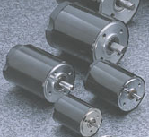 |
FEATURE : |
|
| NOTICE : EVERMO High Duribilty PMDC Micro Motor is only for customer's OEM/ODM orders, so pls contact with our sales engineer by sales02@telstar-tech.com.tw before your samples order released !! Thank you very much ! |
Please contact sales02@telstar-tech.com.tw for more detailed technical spec. data/drawing